
Most campus fiber backbone designs were built for permanence. Splice trays, fixed ODFs, and manual patch panels created stable infrastructure for university networks and enterprise LANs that changed slowly. That model no longer fits reality. Campuses now support hybrid learning, research clusters, IoT, edge compute, and segmented security zones. The physical layer must move as fast as the logical one.
The Operational Cost of Splice-Based Campus Backbones
Splice trays were engineered for durability, not agility. In a traditional campus fiber backbone, every moves/adds/changes event requires physical technician dispatch, manual cable tracing, and a scheduled change window.
The operational impact is measurable. According to BICSI TDMM 14th Edition benchmarks, manual patching error rates in large enterprise LAN environments typically fall in the 2–3% range of annual change events. In a 40-building campus network processing 2,000 fiber changes per year, that error rate produces 40–60 avoidable fault events — each requiring additional dispatch, documentation correction, and extended mean-time-to-repair.
Splice-based environments also resist scaling. Adding capacity often means pulling new fiber, re-terminating bundles, and scheduling disruptive change windows that affect live services. The physical layer becomes the rate-limiting factor in an otherwise virtualized network.
Splice-to-Connector Migration Without Downtime
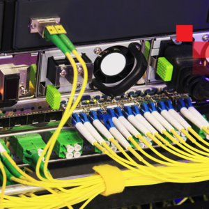 Backbone modernization does not require full infrastructure replacement. A structured splice-to-connector migration enables staged transformation with parallel path deployment between MDF and IDFs, connectorized LC UPC termination replacing permanent splices, and gradual cutover by building or distribution zone.
With a parallel path strategy, downtime-free fiber re-termination is operationally achievable. Traffic migrates to the new connectorized path before legacy splice trays are decommissioned — eliminating the service interruption that has historically made backbone upgrades prohibitive.
Connectorized automated systems operating within ANSI/TIA-568-C.3 campus backbone specifications maintain insertion loss ≤0.8 dB in standard configurations and return loss better than −55 dB (UPC). These values are consistent with ITU-T G.671 Class B connector performance thresholds, preserving carrier-class optical link budgets while adding the modularity that splice-based systems cannot offer.
A typical entry point for enterprise LAN modernization is a 288-port robotic patch upgrade at the campus core — consolidating multiple manual ODF fields into a single programmable switching layer. XENOptics XSOS platform lab testing confirms cross-connect completion in under 60 seconds from API request to verified port state, compared to 2–4 hours for equivalent manual dispatch cycles in multi-building campuses.
Software-Defined Cross-Connect for the Enterprise LAN
The material operational shift occurs when physical connectivity becomes programmable. A software-defined cross-connect replaces manual patching with automated switching: a connection request is submitted remotely, the system calculates the path, the cross-connect completes in under 60 seconds, and the change is logged automatically in an immutable audit record.
Remote troubleshooting becomes immediate. Network teams can verify port state in real time, isolate links without physical tracing, and re-route services without site visits — capabilities that align with IEEE 802.3 network management principles for high-availability infrastructure.
RESTful API management integrates the physical layer into existing NMS and orchestration platforms. Virtual patch panels mirror the live topology, maintaining documentation accuracy that drift-prone manual processes cannot sustain at scale. For regulated environments — education, healthcare, research laboratories — automated logging delivers audit-ready records of every connection and disconnection event, moving change control from spreadsheets to system-enforced workflows aligned with ISO/IEC 27001 asset management requirements.
What This Means for University Networks and Enterprise IT
 Modern campus environments require elasticity at the physical layer. A programmable backbone — compliant with BICSI TDMM structured cabling methodology and built on ANSI/TIA-568-C.3 connectorized architecture — enables outcomes that static splice infrastructure cannot support:
- Rapid research lab turn-ups without physical recabling
- Temporary network segmentation for security incidents or events
- Faster fault recovery with sub-60-second remote re-routing validated in XENOptics lab testing
- Capacity scaling for AI compute clusters without new fiber pulls
- Simplified compliance documentation through automated change logging
From Static Infrastructure to Programmable Asset
Splice trays delivered stability for a different era of campus networking. Today’s campus fiber backbone must deliver stability and agility simultaneously. Software-defined cross-connect, connectorized TIA-568-compliant architecture, and RESTful API management transform the backbone from a fixed wiring system into a managed, software-controlled asset.
For IT directors and network architects evaluating modernization, the diagnostic questions are concrete: How many technician dispatches did your team complete last quarter? What is your current mean-time-to-repair for a fiber fault? How many fiber changes resulted in documentation errors in the past 12 months?
The shift from splice trays to software is not cosmetic. It is a measurable operational transition. XENOptics engineering is available to assess existing campus backbone configurations against TIA-568-C.3 and BICSI TDMM baselines and model the transition path.
Standards Referenced in This Article
- ANSI/TIA-568-C.3 — Optical Fiber Cabling Components Standard
- ITU-T G.671 — Transmission characteristics of optical components and subsystems
- BICSI TDMM, 14th Edition — Telecommunications Distribution Methods Manual
- IEEE 802.3 — Ethernet Standard
- ISO/IEC 27001:2022 — Information Security Management Systems