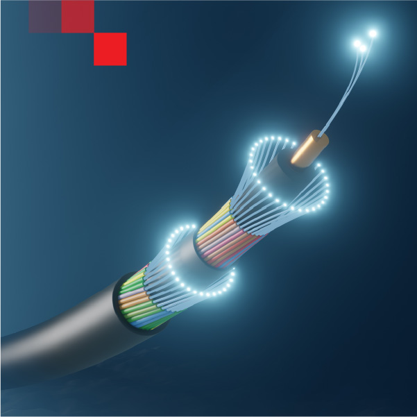
Subsea capacity only moves at the speed of the shore end. If circuit turn-ups at your cable landing station (CLS) still rely on manual patching and scarce maintenance windows, you’re leaving bandwidth—and money—at the waterline. This page shows how to modernize CLS fiber management with a robotic CLS fiber switch and integrated network management, pairing rack-scale density with the security and auditability your operations team demands.
XENOptics builds carrier-class robotic optical switching for mission-critical environments. The platforms deliver dense, connectorized LC/UPC cross-connects; passive-latching optics that hold traffic paths through power events; and field-replaceable modules engineered for live networks. Deployed in a standard 19″ rack, these systems turn meet-me rooms and shore-end racks into API-addressable infrastructure—without a forklift upgrade.
Landing stations juggle SLTE handoffs, terrestrial backhaul diversity, tight change control, and harsh environmental factors. Traditional patch fields make provisioning slow and error-prone. A mispatch or mislabeled jumper can jeopardize SLAs across an ocean.
Modern CLS fiber management replaces manual patching with a robotic cross-connect fabric. What changes immediately:
For compliance, specify platforms qualified to carrier-class standards such as NEBS Level 3, ETSI 300 019-3-2, and temperature cycling per IEC 60068-2-14. That alignment streamlines audits and reduces integration friction with existing facilities standards.
A CLS fiber switch is a robotic optical cross-connect presenting thousands of LC/UPC terminations in a non-blocking matrix. Think rack-scale patching with software brains and service-provider reliability.
What to expect from XENOptics systems:

In practice, a CLS fiber switch sits between SLTE shelves, ROADM/DCI gear, and terrestrial backhaul ODFs. It replaces open patch fields with a closed, inventoried cross-connect fabric that you can reconfigure from your network operations center—or trigger via an automation runbook.
You don’t invest in robotics to click a GUI manually. The ROI comes from CLS network management that ties the hardware to your provisioning, change control, and inventory.
A pragmatic approach centers on four disciplines:
The result: provisioning, re-homing, and restoration move from “send a truck and book a window” to “submit a job and track compliance.”
| Dimension | Manual Patch Fields | Robotic CLS Fiber Switch (XENOptics) |
|---|---|---|
| Provisioning time | Hours to days; technician scheduling | Minutes; queued tasks execute within change windows |
| Risk of mispatch | Medium to high in busy rooms | Very low; port mapping, software validation, atomic execution |
| Port density | Limited by panels and craft access | Thousands of LC/UPC ports per standard 19″ rack |
| Optical budget | Variable; jumper quality and handling | Predictable; connectorized paths, sub-1 dB typical per switch |
| Power events | Patch state depends on humans | Passive-latching retains live paths through outages |
| Maintenance | Craft required; disruptive | In-service module swaps with audit control |
| OPEX impact | Truck rolls; long change windows | Fewer truck rolls; faster turn-ups and re-homes |
Optical figures reflect connectorized, real-world deployments. Always size to your end-to-end attenuation budget.
XENOptics specializes in ruggedized, robotic optical switching for data centers, telecoms, and defense—environments where downtime and guesswork are unacceptable. For cable landing stations, that translates into:

Modern subsea networks deserve shore ends that move at software speed. With a carrier-grade fiber switch and disciplined CLS network management, your landing stations become agile, auditable, and ready for the next wave of capacity.
CLS — Cable Landing Station; shore-end facility where subsea systems hand off to terrestrial networks.
SLTE — Submarine Line Terminal Equipment; terminal gear interfacing the wet plant to shore-side gear.
LC/UPC — Lucent Connector with Ultra Physical Contact; default connectorized interface assumed in XENOptics deployments.
Passive latching — Mechanical/optical design that maintains the optical path without continuous power, preserving live circuits through outages.
A/B path — Dual, diverse fiber routes engineered for protection and maintenance flexibility.
ODF — Optical Distribution Frame; termination/patching hardware often consolidated by a robotic CLS fiber switch.
MACD — Moves, Adds, Changes, Disconnects; routine work automated via CLS network management job templates.
SNMPv3 — Secure management/telemetry protocol used for alarms and state in OSS/NMS integrations.
REST API — Web-based API style used to program cross-connects and fold the CLS fiber switch into automation pipelines.
RBAC — Role-Based Access Control; least-privilege permissions and approvals for zero-trust operations.
NEBS Level 3 — Carrier-class reliability/safety criteria common in telco facilities.
ETSI EN 300 019-3-2 — Environmental class for stationary, weather-protected telecom equipment.
IEC 60068-2-14 — Temperature change/cycling test method used for environmental qualification.
© 2018-2026 XENOptics. All Rights Reserved. Terms of Use.