
Aerospace EMC (Electro Magnetic Compability) test labs invest heavily in RF isolation—shielded chambers, precision instrumentation, carefully controlled environments. Yet a surprising number still rely on manual fiber patching to reconfigure test setups, introducing delays and human error into otherwise tightly controlled workflows.
Why EMC Chambers Still Lose Time on Fiber
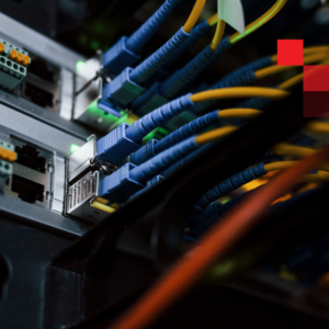
Test campaigns in aerospace EMC labs change frequently. A facility running MIL-STD-461G radiated susceptibility tests one day may switch to DO-160 Section 20 conducted emissions the next—different antennas, DUTs, instruments, and measurement paths cycling through chambers on tight schedules. Each configuration change typically requires someone to physically re-patch fiber connections at the chamber boundary or inside the shielded environment itself.
Manual patching creates three categories of friction:
- Schedule friction: Someone must be physically present, sometimes after-hours or over weekends, to execute a patch change before testing can proceed.
- Error risk: Mis-patches, polarity mistakes, and wrong-port connections happen, especially under time pressure. Industry data suggests manual patching errors contribute to 3–7% of invalid test runs in high-throughput facilities.
- RF process risk: Unnecessary chamber openings and increased handling near sensitive setups can introduce variables that affect test repeatability per IEC 61000-4-3 requirements.
The subtle failure mode is often the costliest: a “small” patching mistake that invalidates a test run. By the time the error surfaces in the data, hours of chamber time have been consumed—and the retest cycle begins.
Chamber Feed-Through Cross-Connect: The Clean Way to Scale
The core design principle is straightforward: separate the fixed chamber penetrations from the switching logic.
In a feed-through architecture, fiber passes through the chamber wall via stable, shielded penetrations. All routing changes happen in a controlled zone outside the chamber—typically a shielded equipment room or meet-me-room-style space adjacent to the test facility. A remote-controlled cross-connect in this zone handles all path reconfiguration.
Reference topology using CSOS-72/144 for aerospace EMC facilities:
| Parameter | Specification |
|---|---|
| Fiber ports | 72 (Simplex LC) or 144 (Duplex LC) |
| Insertion loss | <1.0 dB |
| Return loss | <−55 dB |
| Crosstalk | <−70 dB |
| Wavelength range | 1260–1630 nm |
| Switching time | 36–60 seconds per connection |
| Operating temperature | −40°C to +65°C |
| Control interfaces | RS-232, SNMPv2/v3, Telnet, SSH, REST API |
| Compliance | ETSI 300019, GR-63-CORE, EN/IEC EMC standards |
This approach protects RF isolation in two ways. First, chamber penetrations remain undisturbed—no repeated handling of feed-throughs that could degrade shielding effectiveness over time. Second, fewer door openings mean less physical disturbance near sensitive test setups, supporting the environmental stability requirements of MIL-STD-461G Test Method RS103.
From an operational standpoint, test engineers can reconfigure fiber routes remotely without scheduling a technician to enter the chamber area. The switching infrastructure becomes software-controllable, aligning fiber management with the rest of the automated test environment.
Reduce Unintended Coupling and Keep the Test Environment Predictable
 Labs already avoid copper near sensitive zones for good reason—any conductive element can act as an antenna or introduce coupling paths that compromise field uniformity measurements. The same logic applies to operational tooling and change processes at the chamber boundary.
Non-metallic fiber switching addresses this by minimizing conductive components in areas where RF performance matters most. The CSOS platform delivers carrier-class optical performance: <1.0 dB insertion loss and <−65 dB return loss ensure the switching layer adds minimal measurement uncertainty even as automation replaces manual patch panels.
For labs validating equipment against RTCA DO-160G Section 20 or MIL-STD-461G RE102, maintaining calibrated signal paths is non-negotiable. A well-designed switching architecture preserves path loss budgets while eliminating the variability introduced by repeated manual connections—each hand-mate cycle on a fiber connector can degrade return loss by 0.1–0.3 dB over time.
Laser-Safe Routing and Fewer Hands-On Interventions
Reducing manual handling has safety benefits beyond schedule efficiency. Fewer hands-on interventions mean reduced exposure risk around active optical sources and high-power test instruments—particularly relevant for labs operating Class 3B or Class 4 laser sources in photonics or directed-energy testing.
Laser-safe routing becomes easier to enforce when patching happens remotely. Instead of technicians working at the chamber wall while optical links are live, routing changes occur through a controlled interface with appropriate access controls. Role-based permissions ensure only authorized personnel can modify routes, and all changes require explicit confirmation before execution.
For facilities operating under AS9100 quality management or with DoD contract requirements, remote switching also provides time-stamped logs of every routing change. When test results are later questioned—or when audits require traceability—the records exist automatically, documenting who requested each change and when it executed.
What Changes When Fiber Becomes Software-Controlled
The bottleneck in manual fiber patching isn’t the physical act of mating connectors—it’s the scheduling overhead. A technician needs to be available, travel to the facility, badge into the secured area, and execute the change. That process typically consumes 15–30 minutes at best, and 4–14 hours when changes are needed outside normal working hours.
Remote fiber switching eliminates that scheduling dependency entirely.
The real comparison:
| Scenario | Manual patching | Automated switching |
|---|---|---|
| Daytime, technician available | 15–30 min | ~1 min |
| After-hours or weekend | 4–14 hours (next availability) | ~1 min |
| Multi-port reconfiguration (12 ports) | 30–60 min + scheduling | ~12 min |
Operational ROI shows up in several measurable areas:
 Eliminated scheduling delays: Route updates execute in under a minute regardless of time of day. The 36–60 second switching time per connection is irrelevant compared to the hours saved by removing technician scheduling from the critical path.
Fewer re-tests: Robotic switching eliminates mis-patches. The CSOS executes the same connection identically every time—no polarity mistakes, no wrong-port errors. Facilities report 90%+ reduction in fiber-related test invalidations after deploying automated switching.
Better asset utilization: Chamber time is the scarce resource in most aerospace EMC labs—often valued at $500–2,000/hour when fully burdened. Removing manual patching from the critical path can recover 5–10% of productive chamber hours per month.
Passive-latching continuity: The CSOS uses a latching mechanism that maintains connections even during power loss or maintenance windows—no risk of routes resetting unexpectedly mid-test, protecting long-duration test sequences common in environmental qualification campaigns.
Deployment Scenario: Defense Contractor EMC Lab
A defense contractor operating three shielded chambers for MIL-STD-461G qualification faced a recurring bottleneck: test engineers scheduled 2–3 days in advance, but last-minute DUT availability changes required fiber reconfiguration that couldn’t happen until a technician arrived the next morning.
Before automated switching:
- Average changeover delay: 14 hours (overnight wait)
- Fiber-related test invalidations: 6% of runs
- Chamber utilization: 61%
After deploying feed-through cross-connect architecture:
- Changeover time: <2 minutes (remote execution)
- Fiber-related test invalidations: <0.5% of runs
- Chamber utilization: 73%
The 12-point improvement in chamber utilization—achieved without adding staff or extending operating hours—represented approximately $180,000 in recovered annual capacity across the three chambers.
Next Steps
If manual fiber patching is still part of your chamber workflow, start by mapping the current touchpoints. How many route changes happen per week? How much time does each one consume? How often do patching errors trigger re-tests?
From there, consider what a chamber feed-through cross-connect architecture would look like for your facility.
Request a chamber feed-through switching reference layout for your specific configuration, or share your chamber count and instrument count—we’ll suggest a topology that fits your testing workflow.