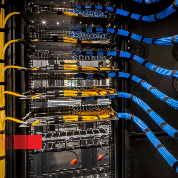
Colocation operators face constant pressure to accelerate tenant turn-ups, cut operating costs, and maintain airtight compliance. Traditional patch panels cannot meet those demands. Remote fiber management uses a robotic optical matrix to replace manual patching, giving colos a high-density, software-controlled layer of connectivity that is fast, repeatable, and audit-ready.
Definition: Remote fiber management is the automation of physical optical cross-connects through a robotic switch fabric. Connections are made mechanically within the switch, commanded by software, without manual patch cords.
Instead of relying on manual patching, a robotic, non-blocking matrix executes cross-connects on command. The switch fabric uses passive latching optics: once a path is made, it is mechanically held without needing holding power. Established light paths survive outages, module replacements, or power cuts.
Operations staff interact via web GUI, REST API, or SNMPv2/v3, with queuing and approval workflows to ensure every action is authorized and logged. No data plane termination occurs—traffic passes purely at the optical layer.
| Matrix | Ports | Managed endpoints/rack | IL | RL | Switch time | Standby | Sleep |
|---|---|---|---|---|---|---|---|
| XSOS-288 | 288 | Up to 3,456 (back-to-back) | ≤0.8 dB | < -55 dB | 35–60 s | ~6 W | 0.1–0.5 W |
| XSOS-576D | 576 | Nearly 7,000 (dual-sided) | ≤1.0 dB | < -55 dB | 24–40 s | ~6 W | 0.1–0.5 W |
| CSOS (compact OSP) | 72–144 | >10,000 fibers per rack (dense builds) | ≤1.0 dB | < -55 dB | 36–60 s | ~6 W | 0.1–0.5 W |
Methodology note: Connectorized configuration, OS2 single-mode fiber, ambient 25 °C. Insertion and return loss measured with calibrated optical power meters. Values reflect typical field deployments; performance may vary with connector quality and handling.
Shared colocation environments demand strict separation of control, airtight records, and minimal attack surface. Remote fiber management addresses all three:
By making every action deliberate, approved, and logged, colos reduce both operational risk and regulatory exposure. Security teams gain verifiable proof of process, while operations staff can still move at speed.

Both patterns fit existing riser and MMR cabling, preserving trunk designs (144F, 96F, 32F, 16F) and sliding-rail racks.
Together, these outcomes deliver both financial and operational resilience: lower cost, higher agility, and stronger compliance.
| Criterion | Manual patch panels | Remote fiber management |
|---|---|---|
| Execute a cross-connect | Hours to days | 36–60 s automated |
| Service continuity on power loss | Risk of human error | Latched optics; traffic stays up |
| Audit &smp; approvals | Paper trails, inconsistent | Queued tasks, four-eyes, immutable logs |
| Density per 19" rack | Dozens–hundreds of ports | 3,456–~7,000 managed ports |
| Power profile | N/A | ~6 W standby; <0.5 W sleep |
Methodology note: Connectorized configuration, OS2 single-mode fiber, ambient 25 °C. Insertion and return loss measured with calibrated optical power meters. Values reflect typical field deployments; performance may vary with connector quality and handling.
Book a 45-minute design session with our solutions team. We’ll scope your first MMR pilot, align guardrails to your compliance framework, and show how to scale floor by floor without re-cabling.
What is a passive latching optical switch?
It is a robotic optical matrix that mechanically latches light paths. Once connected, no holding power is needed, so traffic stays up during outages.
Does switching interrupt active light paths?
No. Established paths remain stable while a new path is created. A 36–60-second operation applies only to the new cross-connect.
How do approvals and audits work?
Every command is queued, requires dual approval, and generates an immutable log entry. This record can be integrated with SIEM for compliance.
What IL/RL budgets should I plan for DWDM vs. SR?
Connectorized deployments show ≤1.0 dB insertion loss and < -55 dB return loss. Design with an extra margin of 1 dB for coherent DWDM paths; short-reach typically tolerates higher.
Can I survive a power loss?
Yes. Passive latching holds light paths mechanically. Even during full power outages, existing traffic is not interrupted.
© 2018-2026 XENOptics. All Rights Reserved. Terms of Use.