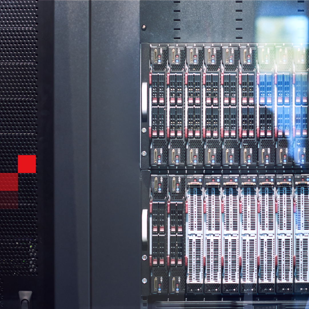
Meet‑Me Rooms (MMRs) are where carriers, clouds, and tenants interconnect. Manual fiber patching slows turn‑ups, raises error risk, and strains SLAs. Robotic fiber switching turns the MMR into a software‑controlled, auditable Layer‑0 fabric. A robotic cross‑connect executes queued optical tasks in 24–60 seconds and keeps established paths latched if power drops. Result: faster provisioning, fewer human touches, and predictable optical budgets.
Definition — Robotic fiber switching
A rack‑mount optical cross‑connect that uses a robotic manipulator and passive latching to mate LC connectors under software control (GUI, REST, SNMPv3). It supports task queues, shortest‑path routing across multi‑chassis topologies, and full change logs. Live connections remain optically latched during power loss.
Modules. XSOS/CSOS systems pair an Optical Fiber Switch (robotic matrix + latch) with a Main Control Unit (controller, power, drivers).
Controls and workflows.
The passive latch maintains established optical paths without power; the system draws power only while switching (typ. 6 W idle; 0.1–0.5 W deep sleep). Operate via Web GUI, REST, SNMPv2/v3. Telnet/SSH are for vendor troubleshooting only and not exposed in customer deployments (per deployment policy).

| Attribute | Value | Conditions |
|---|---|---|
| Switching time | 24–60 s | Model dependent; connectorized; single mode |
| Insertion/Return Loss | ≤ 1.0 dB (XSOS 576D connectorized); ≤ 0.8 dB typical (XSOS 288 connectorized); RL < -55 dB (UPC) | Field values from connectorized configs; UPC is standard offer; APC availability varies* |
| Continuity | Passive latching | Established paths persist on power loss |
| Interfaces | REST API, SNMPv3, Web GUI | Separate management network recommended; SSH/Telnet reserved for vendor support |
* Expert note: Return loss is expressed as “higher than” a positive value. Current standard offering uses UPC connectors (< -55 dB RL). APC variants may appear in some datasheets; confirm availability with your XENOptics rep before budgeting.
Methodology
Connectorized, single‑mode LC measurements over 1260–1630 nm band; switching time measured at room temperature; IL values reflect connectorized field configuration (not spliced); RL values reflect UPC polish in current offer; standby and sleep power from product briefs. Meters and environment: lab‑grade optical source/power meter, 21–25 °C, 35–65% RH. Source list: product briefs and quick‑start; internal measurement method summarized.
| Metric | Manual | Robotic | Improvement |
|---|---|---|---|
| Provisioning time per connection | 15–30 min | 24–60 s | ≈ 36× faster |
| Patching error rate | 2.7% | 0.02% | – 99% |
| Fiber ops labor (per MW) | 2.0 FTE | 0.8 FTE | – 60–65% |
| Power resilience | Unlatched | Latched | No re-seat needed |
| Idle/sleep power | n/a | ~6 W / 0.1–0.5 W | Low overhead |
Source: Internal analysis (2025), method summarized. Provisioning/idle/sleep from product briefs; error and labor outcomes from production deployments (aggregated/anonymized).
Note: If you require third‑party‑verifiable figures for a specific site, we can run a pre‑pilot with before/after metrics and share the protocol up front.

Scope. 20 MW facility; MDF + multi‑floor MMRs; phased automation across seven duplex units.
Before → After (12–14 months):
Method note. Site‑level metering with IT kW vs. total kWh; month‑over‑month comparisons normalized for ambient. Change tickets cross‑checked against NMS logs to confirm automation share of impact.
Evidence label: Internal analysis (method summarized); customer anonymized; no logos.
Treat the MMR like a switch fabric you can program: APIs let orchestration pick shortest paths, schedule queued jobs, and keep topology views in sync with reality. As 800G and multi‑tenant AI footprints scale, automated Layer‑0 becomes the only practical way to align physical cross‑connects with intent‑based workflows.
Bring one floor’s MMR layout (A/B, trunks, target port count). We’ll propose a queue‑driven topology, density per rack, and a measurement plan for a low‑risk pilot. Book a demo.
What happens to active circuits during switching?
Established circuits remain latched during power events. When you change a specific connection, that path is physically re‑mated; plan a short maintenance window or use a make‑before‑break method via a pre‑provisioned alternate path. Other circuits on the frame are unaffected.
How do queued tasks and four‑eyes approvals work?
Operators submit connects/disconnects; the NMS places them in a remaining‑tasks queue and executes in order. Use role‑based controls so a second operator approves before execution. All actions are time‑stamped and retained for audit.
Can I visualize shortest paths and capacity in the MMR?
Yes. The NMS computes a route between elements and shows it in a topology view. Port tables and interconnection lists update in real time.
What IL/RL budgets should I plan for?
Plan ≤ 0.8–1.0 dB per robotic cross‑connect in connectorized single‑mode. Use < -55 dB RL (UPC) for design; APC availability varies—verify before committing. Keep jumper counts low and inspect connectors to stay inside end‑to‑end budget.
Do I need out‑of‑band management?
Run the Web/REST/SNMP interfaces on a dedicated management network. CLI (Telnet/SSH) is reserved for vendor support; do not expose it in normal operations.
© 2018-2026 XENOptics. All Rights Reserved. Terms of Use.