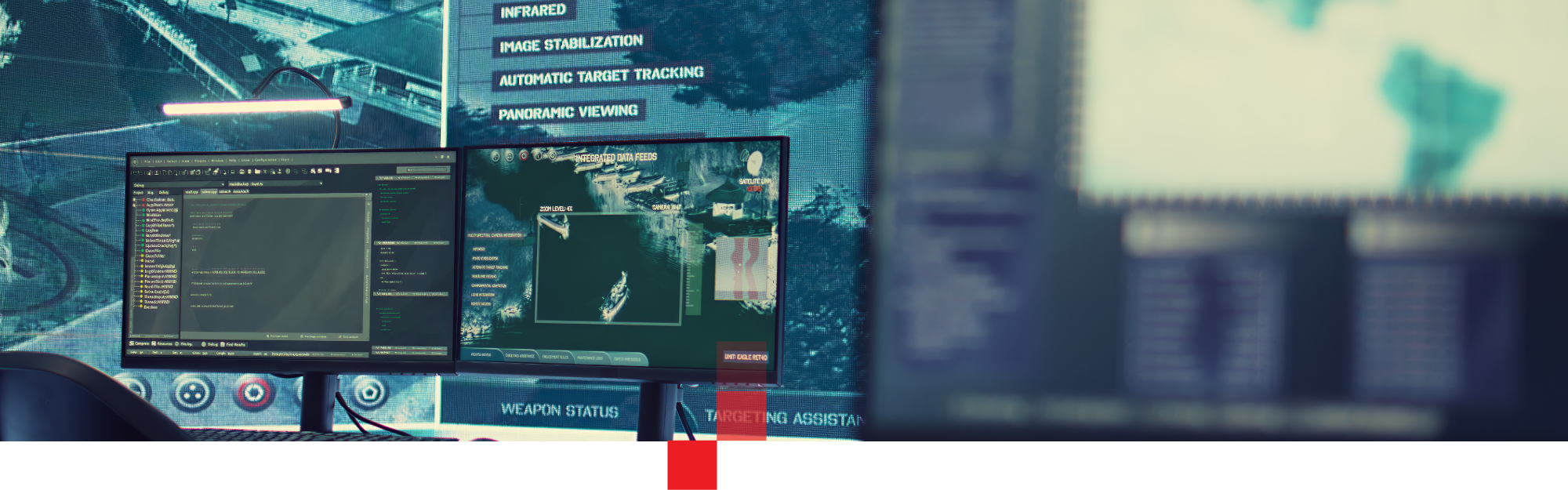
Mission networks now span deserts, mountains, oceans, and orbit—connecting fixed HQs, mobile command posts, sensor arrays, and classified data centers into a single mission-critical fiber network. A carrier-class robotic fiber switch with remote fiber management turns that physical layer from a fragile patch field into a programmable, resilient asset you can control from a secure operations center.
A carrier-class robotic fiber switch architecture gives defense operators assured, programmable connectivity at the optical layer while keeping people out of harm’s way.
Modern mission networks are a mesh of:
All of them ride on fiber. Yet the operating model at Layer 0 is still: pull a jumper, read a label, plug it somewhere else, and hope nothing adjacent gets disturbed.
That breaks down when:
Every manual move adds risk. Mis-patches, undocumented cross‑connects, and accidental pulls remain common root causes of fiber incidents in large environments. A mission-critical fiber network cannot depend on truck rolls and jumpers whenever the topology has to change.
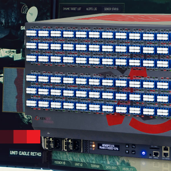
At the core is a robotic optical cross‑connect—a compact chassis that turns hundreds of LC ports into a fully addressable fabric. XENOptics XSOS and CSOS platforms integrate:
Each connection is a real LC connector, placed and latched by the robot. Optical performance in the standard connectorized configuration is carrier‑grade:
A single cross‑connect completes in 36–60 seconds across both XSOS and CSOS families, so even complex re‑patch jobs finish in about the time a human would need just to walk to the rack.
The fabric uses passive mechanical latching, not active relays. Once a path is established, it stays physically connected even if local power fails. That behavior underpins true power-independent traffic at Layer 0.
Defense deployments are not climate‑controlled labs. They are street cabinets, pad‑mounted shelters, trailers, ship racks, and exposed sites.
The compact CSOS line is explicitly designed for harsh Outside Plant environments:
XSOS systems share the same environmental philosophy and support deployment in street cabinets and harsh edge locations under ETSI 300019 Class 3.2 and NEBS 3 environmental standards.
Mechanically, both families are built for long service in tough conditions:
The platforms are engineered for a 20‑year service life, matching the lifecycle of fiber infrastructure rather than short server refresh cycles.
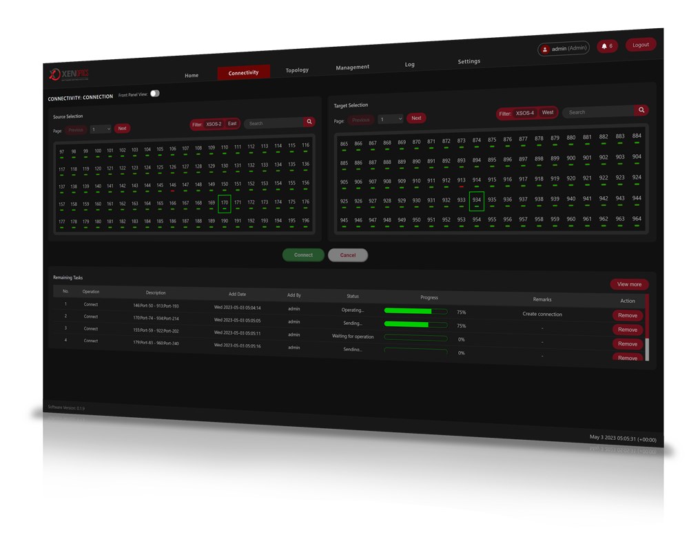
Once the chassis is wired, Layer‑0 work becomes a software problem instead of a field job.
A combined local web UI, Element Management System (EMS), and Network Management System (NMS) let operators:
All changes are executed as discrete jobs. EMS and NMS keep designs, inventories, and live state synchronized, so what you see in software matches the reality in the rack.
Interfaces include:
With this model, you get genuine remote fiber management: reconfigurations flow from a secure operations center, not from ladder tops, manholes, or contested sites.
Zero‑trust is now standard practice at higher network layers. Robotic switching extends that mindset down to the optical plant.
Key properties:
Instead of trusting that “no one touched the cable,” you get a complete, auditable history of every physical path change—aligned with defense governance and audit expectations.
Defense customers typically tier carrier‑class robotic fiber switch deployments across the architecture:
Across all tiers, hot-swap modules allow you to replace power supplies, controllers, or fiber cassettes without taking down live circuits—critical when sites are hard or dangerous to reach.
From XENOptics customer deployment data in commercial and government networks, three categories of benefit stand out:
Based on XENOptics customer deployment data, these factors deliver a typical ROI window of 12–18 months, driven mostly by labor savings, reduced error incidents, and more efficient port utilization—not speculative assumptions.
Any platform in a mission environment must meet stringent technical and compliance expectations.
XSOS and CSOS systems are built as carrier‑class elements and qualified to:
They expose standard LC UPC/APC connectors in the normal configuration, so they slot into existing ODFs, cassettes, and trunking without exotic components.
Management uses mainstream protocols (HTTPS, SNMPv2/v3, REST), making it straightforward to plug into existing NMS, DCIM, or custom orchestration tools and to enforce least‑privilege role models around who can operate the fabric.
Under the covers, the hardware is modular. Power supplies, controller boards, and fiber modules are hot-swap modules, so most failures can be resolved at the rack without impacting live circuits or shipping a full chassis back to a depot. Combined with the 20‑year service life design goal, this creates a low‑touch platform that can stay in place for most of a facility’s life.
Layer 0 has been the last manual frontier in many mission networks. A carrier‑class robotic fiber switch fabric closes that gap.
You gain:
A practical next step is to identify one or two high‑impact sites—such as a regional hub plus a forward shelter—and model the gains from replacing manual ODFs with a carrier-class robotic fiber switch deployment. From there, you can define standards for which tiers use XSOS, which use CSOS, and how remote fiber management integrates with your existing C2 and NOC tooling.
Work with the team to map where carrier‑class robotic fiber switches fit into your bases, shelters, and remote cabinets. Start with a limited pilot—one HQ, one forward node, one harsh OSP location—and prove how much risk, time, and cost you can remove from your mission‑critical fiber network.
© 2018-2026 XENOptics. All Rights Reserved. Terms of Use.