
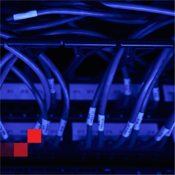
Municipal open-access networks depend on a simple contract: the infrastructure owner builds once, and multiple ISPs deliver service over shared fiber. That contract breaks down at Layer 0 when every new customer, provider swap, or reroute requires a truck roll, a technician, and a manual patch action that no one audits consistently.
Robotic fiber switching brings change control to the physical layer. It replaces ad hoc patching with governed cross-connect operations—executed remotely, logged automatically, and scoped to tenant boundaries. This reference guide maps the operational model, deployment architecture, and acceptance criteria for municipal operators evaluating automated optical switching at the network edge.
Performance targets and system behaviors described in this guide reflect XENOptics laboratory validation and platform specifications. Deployment outcomes will vary based on network design, fiber plant condition, and operational maturity. All specification values reference published XENOptics product datasheets.
Open access separates the infrastructure owner from the service providers. That separation creates healthy competition, but it also creates constant physical-layer change.
At the municipal edge, that change shows up as:
Manual patch panels do not scale to that operating model. They are slow to update, hard to audit, and easy to mis-patch when teams are under time pressure. A 2019 BICSI survey of outside plant professionals found that documentation drift—where physical connections no longer match records—was cited as one of the most persistent sources of operational risk in multi-tenant fiber environments.
Municipal operators increasingly treat physical routing as an operations problem, not a "hands and labels" problem.
Robotic fiber switching replaces a manual patch action with a controlled, logged task. Instead of dispatching someone to move jumpers, the operator or tenant ISP executes a cross-connect remotely through a management interface.
In practical terms, automated optical switching platforms enable:
This approach fits open access because it converts fiber routing into a repeatable, permission-scoped workflow. It fits edge sites because edge sites rarely have staff on hand when a municipality needs a change executed within minutes.

Most municipal programs do not need a single large-scale transformation. A staged approach that targets the highest-churn and highest-risk locations first delivers faster operational return.
Use compact switching systems where crews struggle to coordinate site access or where truck roll costs dominate the operating budget. Focus on provider handoffs, customer activations, and rapid reroutes after localized fiber damage.
For edge deployments, align hardware qualification to environmental expectations outside a controlled data hall. ETSI 300 019-1, Class 3.2 (weather-protected locations with restricted environmental control) provides a recognized baseline for temperature range, humidity, and vibration tolerance in street cabinets and building risers.
Concentrate cross-connect density where multiple trunk routes converge. Use higher-density switching platforms to standardize ISP handoffs and manage capacity allocation across tenant boundaries.
At aggregation points, ITU-T G.671 defines the optical interface parameters—including insertion loss, return loss, and wavelength-dependent attenuation—that govern how many switching stages a link budget can absorb. These parameters should inform the number of cascaded switch elements between any two endpoints in the network design.
Treat provider boundaries as controlled connection domains. Allocate ports and routes as wholesale resources managed through policy, not as ad hoc patch decisions made under time pressure.
TIA-568 and TIA-758-B (Customer-Owned Outside Plant Telecommunications Infrastructure Standard) provide structured cabling frameworks that apply to municipal interconnect architectures. Aligning port naming, fiber identification, and documentation practices to these standards reduces integration friction when onboarding new ISPs.
Open access works best when it runs like a managed queue, not a series of informal requests.
A governed workflow for wholesale fiber provisioning follows five stages:
This is where carrier ODF automation becomes operational. The organization stops managing patch cords and starts managing a governed inventory of ports, links, and authorized actions.
Municipal networks succeed or fail based on how they handle multi-tenant operations. The hard part is not the fiber itself. The hard part is avoiding conflicts when multiple ISPs share physical infrastructure.
A robust multi-ISP fiber routing model uses four controls:
Port allocation by tenant. Assign port pools per ISP or per service class. Reserve dedicated resources for municipal critical services (traffic management, public safety backhaul, SCADA connectivity).
Tenant-scoped permissions. Each ISP creates connections only within its allocated ports. Any action affecting shared trunks or inter-tenant boundaries requires operator-level approval.
Standard handoff patterns. Define repeatable handoff templates for common service types—residential GPON, business Ethernet, point-to-point wavelength services. Templated handoffs reduce one-off design decisions that introduce patching errors.
Evidence by default. Log every action. Treat the audit log as a deliverable product you provide to ISPs as part of the wholesale service, not as an internal-only record.
When these controls are implemented, a municipality can support rapid provider changes without dispatching technicians to cabinets. In mature workflows, routine service activation targets completion in under 50 seconds because the work becomes "select route → approve → execute," not "schedule site access → drive → patch → label → verify."
Most disaster recovery planning stays at Layer 3—routing protocols, path redundancy, and orchestration software. Municipal programs also need a Layer 0 recovery capability for scenarios where the physical fiber path itself is damaged.
Fiber damage is a routine risk in municipal environments. Construction cuts ducts. Cabinets flood. A vehicle strikes a pole carrying aerial fiber. When a physical route fails, logical rerouting only helps if an alternative physical path exists and can be activated.
Robotic switching supports a Layer 0 DR approach:
Pre-built alternate physical paths. Define primary and secondary routes for critical municipal sites during network design. Maintain those routes as ready-to-activate entries in the switching platform inventory—not as diagrams in a binder that may be outdated when the incident occurs.
Rapid execution under pressure. Execute a pre-planned cross-connect change in under 60 seconds (CSOS platform specification), compared to the hours typically required to coordinate site access, dispatch a technician, and complete a manual reroute.
Repeatable DR playbooks. Build "if route X fails, switch to route Y" procedures as named operations in the management system. Practice them during planned maintenance windows to validate optical performance on the alternate path before a real incident forces the change.
This matters for municipal systems that depend on upstream facilities, regional interconnects, or local micro data centers. In those environments, disaster recovery starts with physical path control. Logical failover cannot restore a service if the only available physical route is the one that was damaged.
Open-access networks carry mixed traffic with mixed performance expectations. Robotic switching must protect both the optical link budget and service continuity during and after switching operations.
Use these acceptance criteria when qualifying a switching platform for municipal deployment:
| Parameter | Target | Automated process |
|---|---|---|
| Switching time per cross-connect | 36–60 seconds | XENOptics CSOS-72/144 platform specification |
| Insertion loss (connectorized, 288-port class) | ≤0.8 dB | XENOptics XSOS-288 datasheet |
| Insertion loss (connectorized, 576-port class) | ≤1.0 dB | XENOptics XSOS-576D datasheet |
| Return loss (UPC connections) | <-55 dB | ITU-T G.671, §5.2 reflection parameters |
Evaluate system behavior during power events and field maintenance:
One important boundary that builds trust with engineers and procurement teams: robotic switching is a physical cross-connect tool, not a diagnostic instrument. It does not replace OTDR testing, connector inspection, or optical power measurement. It changes physical routes. It makes those changes controlled, repeatable, and auditable.
| Operational dimension | Manual patch panel | Robotic switching workflow |
|---|---|---|
| Provisioning speed | Dependent on dispatch scheduling and physical site access | Remote execution; routine changes complete in 36–60s |
| Change consistency | Varies by technician skill and workload | Governed by standard route planning and sequential task queue |
| Audit trail | Often incomplete; relies on manual labeling compliance | Full log of every connect/disconnect with user, timestamp, and route |
| Tenant boundary enforcement | Difficult to enforce physically; relies on trust and labeling | Enforced by port allocation rules and tenant-scoped permissions |
| DR readiness | Dependent on technician availability and site access | Pre-planned paths executed through repeatable playbooks |
| Documentation accuracy | Degrades over time; requires periodic physical audits | Synchronized automatically; inventory reflects actual state |
Municipal operators rarely manage fiber switching in isolation. The switching layer must integrate with the broader NOC and OSS environment.
A web-based GUI supports day-to-day provisioning, route visualization, system monitoring, and administration. This is the primary interface for operators and authorized tenant users managing cross-connects and reviewing system state.
A REST API enables integration with service order management, OSS/BSS platforms, and custom provisioning workflows. Use the API when cross-connect operations need to be triggered programmatically as part of a larger service activation sequence.
SNMPv2/v3 integration allows the switching layer to appear in existing network monitoring and alerting stacks (e.g., PRTG, Nagios, Zabbix, or enterprise NMS platforms) alongside routers, switches, and other managed infrastructure.
Treat access control as part of the wholesale product. Each ISP tenant receives scoped visibility into actions taken within their allocated port domain, with full audit history exportable for their own compliance needs.
A note on management access: some platforms expose legacy interfaces such as Telnet or SSH for internal diagnostics and troubleshooting. These should not be positioned or used as customer-facing access methods. Tenant and operator control should rely on the GUI, REST API, and SNMP interfaces.
If you operate or plan a municipal open-access fiber network, start with one edge cluster where provider churn and truck roll costs create the most operational friction. Map your tenant boundaries, define your top five provisioning workflows, and validate the acceptance criteria that matter: provisioning time, switching time, audit completeness, and link-budget impact.
Then extend the same governed operating model to aggregation PoPs and interconnect zones.
© 2018-2026 XENOptics. All Rights Reserved. Terms of Use.